■ Modbus communication
Signal or dual MODBUS modules may be included in the Hurko electric actuator to provide remote serial communication to
the control functions and for status feedback data. The field network uses an RS485 data highway, either 2 or 4 wires, and
can be duplicated where redundancy is required. The communication is half duplex and the protocol used is Modbus RTU with
data rates up to 38 K baud. The actuator variables necessary to set up the system are programmable over the infrared data
link.
Modbus module advantages:
■ cable cost reduction
■ installation cost reduction
■ simple to configure
■ simple to use
■ widespread open standard protocol
■ many compatible devices available
■ redundant configuration available
HURKO-MODBUS actuators equips a Modbus board which supports the communication protocol of Modbus RTU . The Modbus board makes use of RS485 interface and can operate in either 2(for half duplex) or 4 wire mode(for full duplex), and supports baud rates up to 38.4 kBit/s. Master and slave devices: Max. 247 slave devices connected to one bus, withoutrepeaters max. 32 slave devices.
If the security is required highly for the environment,a redundant connection between the actuators and the DCS can be established by using a second fieldbus cable. And two Modbus boards must be equipped in the actuator, respectively corresponding to bus highway1 and bus highway2. In this way , the communication can be swich to highway2 at once when the highway1 happen trouble.
Modbu master can send the commands which make the actuator carry out OPEN, CLOSE, STOP and ESD.The master can also read the status , setting parameter and some alarm information.
HURKO-MODBUS terminal definition in actuator’s connection box for user:
Terminal umber of actuator’s connection box |
Explaination
|
|
“21”
|
Termination resistance A of the Modbus boardⅠ
|
|
“16”
|
Terminal A of the Modbus boardⅠ
|
|
“17”
|
Terminal B of the Modbus boardⅠ
|
|
“24”
|
Termination resistance B of the Modbus boardⅠ
|
|
“18”
|
Terminal COM. of the Modbus boardⅠ
|
|
“46”
|
Termination resistance A of the Modbus boardⅡ (See Note )
|
|
“14”
|
Terminal A of the Modbus boardⅡ (See Note )
|
|
“15”
|
Terminal B of the Modbus boardⅡ (See Note )
|
|
“47”
|
Termination resistance B of the Modbus boardⅡ (See Note )
|
|
“30”
|
Terminal COM. of the Modbus boardⅡ (See Note )
|
|
“29”
|
Earth Terminal of the Modbus boards
|
Table 2.1: The terminal definition in actuator’s connection box
Note:1、Half duplex mode:Terminal 16 and terminal 14 are connected at inner . Terminal 17 and terminal 15 are connected at inner .
2、Full duplex mode:Terminal 16 and terminal 24 send out the bus signals from the actuator, and terminal 46 and terminal 47 take in the bus signals from the actuator.
3、Redundant mode(only half duplex):Terminal 16 and terminal 17 are general chunnel. And terminal 14 and terminal 15 are redundant chunnel.
■ The cable for the communications
Only cables according to the recommendations of EIA 485 standard should be used for Modbus wiring.
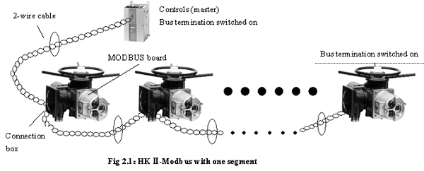
A maximum of up to 32 Modbus devices may be connected in one segment(refer to Fig 2.1 ).If more nodes are to be connected to one Modbus network, several segments must be connected with repeaters.
The bus cable must be laid at a distance of at least 20 cm from other cables.It should be laid in a separate, conductive, and earthed cable trunking.
It must be ensured that no potential differences can occur between the indi-vidual devices on the Modbus (perform a potential equalisation).
Recommended cable specification for Modbus
Screening: CU shielding braid or shielding braid and shielding foil
Impedance: 135 to 165 Ohm, at a frequency of 3 to 20 MHz.
Cable capacity: < 30 pF per metre
Cable diameter: >0.64mm
Cross section: >0.34 mm², conforms to AWG 22
Loop resistance: <110Ω per km
For more information of our Modbus Valve Actuator/Motorized Valve,please feel free to contact us,thanks!


